
Cabinet Assembly: The Retro
Parts List:
1.69" LCD: This is the display screen for your arcade kit, where the games will be displayed.
Controller Board: The controller board is a crucial component that allows you to interact with and play games on the arcade.
Main Board: The main board sends the controller, LCD, LED, and speaker connections to the correct pins on the Raspberry Pi Zero W.
3D Printed PETG Cabinet Parts: These are the custom 3D printed parts that make up the cabinet structure of your arcade.
LED: The LED provides backlighting for the marquee for your arcade, enhancing its visual appeal.
LED Holder: This component securely holds and positions the LED within the arcade cabinet.
Coin Door: The coin door is a decorative and functional element that adds an authentic touch to your arcade.
10cm 8 Pin Rainbow Cable: This cable is used for connecting the LCD to the main board within your arcade kit.
Grey 10-Pin Flat Ribbon Cable: This cable is for connecting and transferring data between the controller board and the main board.
Various Screws (5mm, 12mm, 10mm): These screws are used for securing different parts of your arcade cabinet during assembly.
Micro SD Card and Adapter: The micro SD card and adapter are used for storing the operating system and games for your arcade.
USB-C Extender Right Angle Adapter: This adapter allows you to extend the USB-C connection for your arcade kit to make it easier to charge the battery.
Super Glue: Provided for optional use during assembly to secure certain components in place more permanently.

Step 1: Unboxing and Parts Inventory
Unbox the kit and lay out all the parts on a clean, flat surface.
Ensure that you have all the necessary components listed in the parts list.

Step 2: Install Magnets on the Back Cabinet Door
Locate the back cabinet door.
Press-fit the two magnets into the holes at the top and bottom of the door.
Optionally, you can add a small amount of super glue to secure the magnets in place.

Step 3: Attach LCD Screen to Mount Piece
Use the provided silver screws to attach the LCD screen to the LCD mount piece.

Step 4: Assemble Front LCD Holder
Apply the front LCD holder piece and use the black screw to connect it to the two plastic pieces.

Step 5: Connect LCD Assembly
Plug the LCD assembly into the designated holes in the cabinet side.

Step 6: Connect Control Panel Overlay
Plug the control panel part into the side of the cabinet.

Step 7: Prepare the LED Assembly
Locate the 3D printed piece that holds the LED.
Attach the LED holder to the LED and slide the LED into place in the 3D printed piece.

Step 8: LED wiring
Run the LED wires through the side of the arcade cabinet
Use some super glue to hold wire inside the channel groove in the cabinet side

Step 9: Attach LED Assembly
Connect the LED assembly into the designated holes in the cabinet side.

Step 10: Secure Top Magnet Assembly
Attach the top piece containing one of the magnets to the top of the cabinet side.

Step 11: Install Marquee
Connect the marquee transparent piece into the cabinet side.
Ensure that the top and bottom angles align with the LED assembly piece.
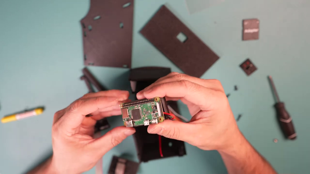
Step 12: Connect Raspberry Pi Zero W to PiSugar Battery
Note: Both Raspberry Pi Zero W and PiSugar battery are not included and must be purchased separately.
Align the pins on the underside of the Raspberry Pi with the pin connectors on the PiSugar board.
Use the bottom two screws that came with the PiSugar battery to secure the connection.

Step 13: Secure PiSugar and Raspberry Pi
Align the connector bar to the top of the PiSugar and Raspberry Pi so that the holes line up.
Screw in the two included screws and apply the two small nuts to lock them in place.

Step 14: Install USB-C Right Angle Adapter
Plug the included USB-C Right Angle Adapter into the PiSugar battery to allow for charging of the battery.

Step 15: Connect Controller Board
Connect the controller board to main board using the grey ribbon cable.

Step 16: Install Controller Assembly
Place the controller board assembly so that the board fits into the slot on the arcade cabinet side.
Press fit it into the cabinet side. You can apply super glue to the holes for a permanent assembly.

Step 17: Plug Main Board into Raspberry Pi Zero W
Plug the main board into the pin headers on the Raspberry Pi Zero W.

Step 18: Connect LED Wires
Place the LED wires into the blue terminals on the main board and screw them down to secure in place. Red wire to the + icon on the board and black wire to the - icon on the board.

Step 19: Connect Rainbow Cable to Main Circuit Board
Attach the rainbow cable to the main circuit board, matching the wire colors to the labeled pins on the board.

Step 20: Insert MicroSD Card
After following the software setup instructions to install the OS, insert the microSD card into the Raspberry Pi Zero W.

Step 21: Assemble Cabinet
Plug the board assembly into the side of the arcade cabinet.
Connect the kickplate and base plate into the side of the arcade cabinet.
Continue working up the cabinet until all pieces have been pressed into place.

Step 22: Attach Cabinet Back
Attach the cabinet back using the magnets you installed earlier.
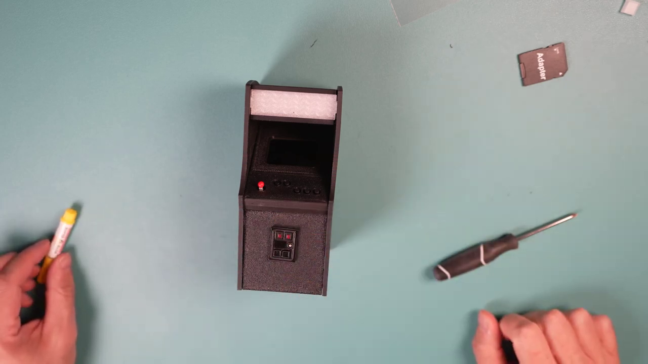
Step 23: Completion
Congratulations, you've completed the assembly of your 6" arcade kit!