
Circuit Boards: Soldering
Parts List
LCD
240x280 1.69” Color TFT
8 pin right angle header
Controller Board
SMD 10mm x 10mm 5 way switch
(5) 6mm x 6mm x 8mm Momentary Tactile Push Buttons
2x5 10 Pin Straight Male Shrouded Header
Main Board
PCB Mount 8 Ohm 0.5W Speaker
Mini PAM8403 5v Audio Amplifier Board
2x5 10 Pin Straight Male Shrouded Header
2 pin Terminal Block Connector
1uF 50V Capacitor
0.033uF Polyester Film Capacitor
220 Ohm Resistor
150 Ohm Resistor
10x20 Pin Double Row Straight Female Pin Header
8 Pin Right Angle Header
(3) 2 Pin Male Headers
Assembly Instructions
LCD Soldering

Step 1: Placing Pins
Place the 8 pin header into position making sure the header connectors are located on the backside of the LCD screen.

Step 2: Solder Pin Header
Solder the pin header into place, making sure not to get soldering iron tip too close to the LCD screen.
Controller Soldering

Step 1: Align and Solder the Joystick
Make note of which 2 pins are futher away from the other 4 pins and make sure that aligns properly with the solder pads on the board.
Solder the 5 way joystick to the controller board, making sure solder flows between the pad and connectors on the joystick.

Step 2: Position and Solder Pushbuttons
Plug the Momentary Tactile Push Buttons into their locations on the board. It can be easier to get them in if you first straighten the pins a little with tweezers or pliers.
Solder the buttons into place.

Step 3: Position and Solder Shrouded Header
Place the 10 Pin Shrouded Header into position on the top of the board, making sure to align it so that the notch in the shroud matches the pattern shown on the underside of the board.
Solder the shrouded header into place.
Main Board Soldering

Step 1: Position 2 Pin Headers
Place the (3) 2 pin headers into position on the board as shown in the photo.

Step 2: Solder Pin Headers and Audio Amplifier
Position the Audio Amplifier as shown in the photo.
The right channel of the Audio Amplifier board does not need to be hooked up as this system only has a mono speaker.
Snip the excess pin header off the Audio Amplifier once soldered into place.

Step 3: Place 0.033uF Capacitor
The 0.033uF Polyester Film Capacitor is placed into position C1 on the board and it doesn’t matter which leg goes into which hole on the board.
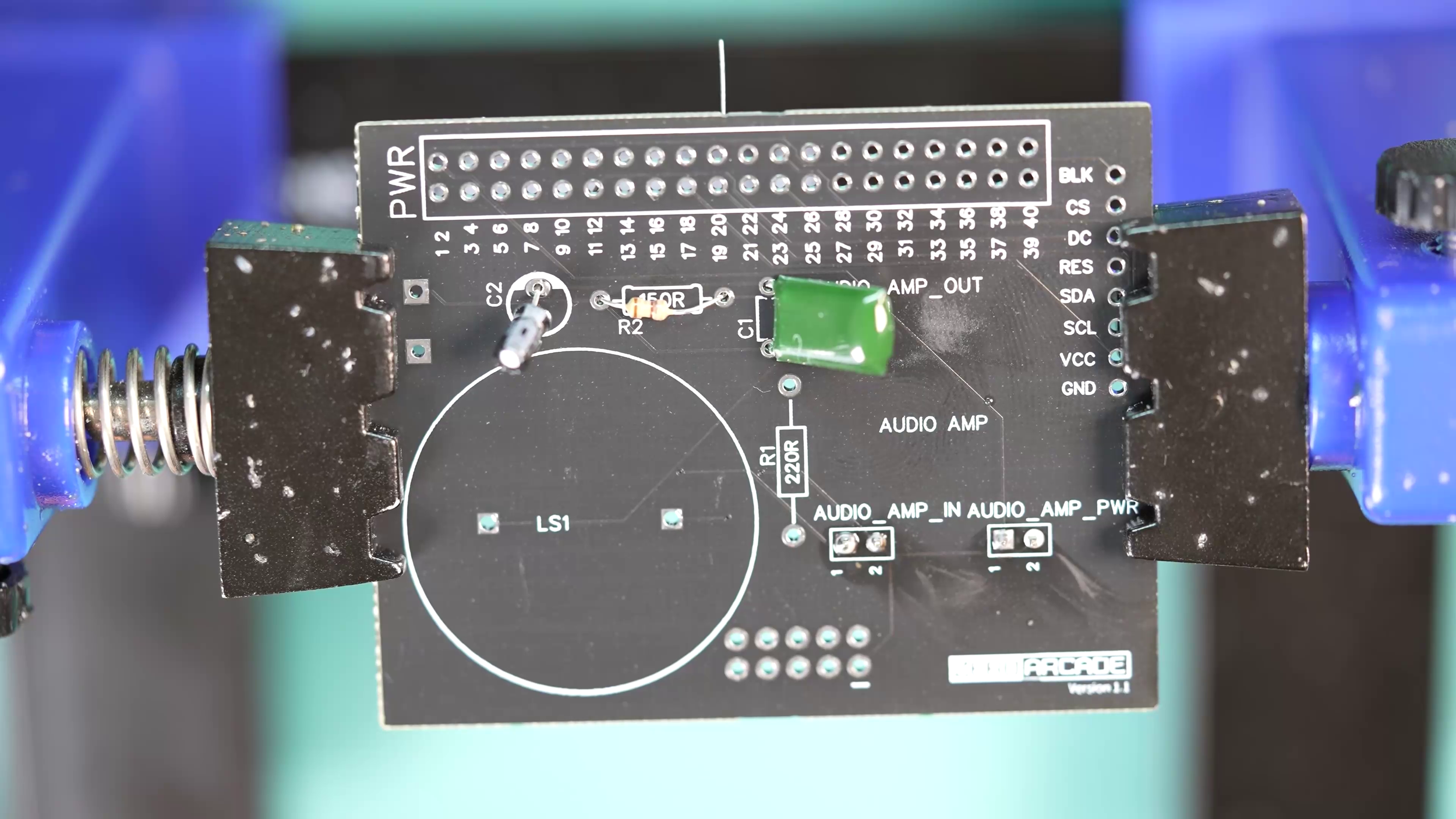
Step 4: Place 1uF Capacitor
Place the 1uF 50V Capacitor into position C2 and unlike the other capacitor, make sure the longer leg of the capacitor goes into the hole marked with a + icon.

Step 5: Place 150 Ohm Resistor
Place the 150 Ohm Resistor into position on the board.
It doesn’t matter which direction you put the resistor into place.

Step 6: Place the 220 Ohm Resistor
Place the 220 Ohm Resistor into position on the board.
It doesn’t matter which direction you put the resistor into place.

Step 7: Solder Capacitors and Resistors
Solder all the Capacitors and Resistors into place.
Trim the excess wire from the components so they’re flush with the soldering.

Step 8: Solder 10 Pin Shrouded Header
Solder the 10 Pin Shrouded Header into position, making sure that the alignment of the header matches the diagram on the circuit board.

Step 9: Solder the 10x20 Pin Double Row Straight Female Pin Header
Solder the 40 pin header to the board and make sure you’re placing it on the correct side of the board.

Step 10: Solder Speaker
Solder the two pins of the speaker to the board.
It doesn’t really matter which pin goes in which hole.

Step 11: Solder 8 pin Right Angle Header
Solder the header to the board while making sure that you are placing it on the correct side of the board before soldering.

Step 12: Solder 2 pin Terminal Block Connector
Solder the terminal block where the wire inputs are facing the outside of the board.